eagleUp simplifies the placement of the component models on your board but you still need to provide the models for every device. Modeling an electronic device is simple and takes only a few minutes, if you follow the proper order. To help you I will detail on this page how I model a simple and a complex device. You can also import mechanical parts like connectors and switches from the manufacturer’s model.
Modeling a part tutorials
The videos shown here follow the text tutorial that you can find below in the page. Here are a couple of keyboard and mouse tricks used in the video :
- left mouse button = action
- right mouse button = contextual menu
- hold center mouse button = rotate around the device
- mouse wheel = zoom in and out
- ctrl + move = duplicate (in translation)
- ctrl + rotate = duplicate (in rotation)
- type in the value directly and press enter to validate
- Del = delete an object
- ctrl + A = select all
Basic resistor model
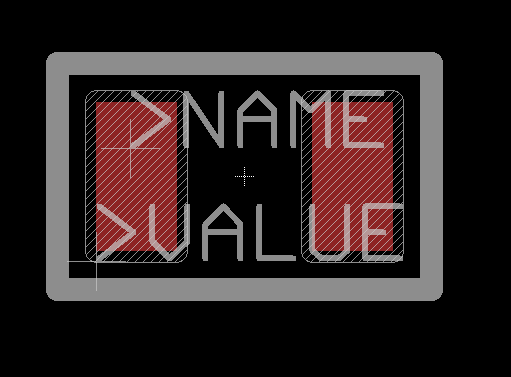
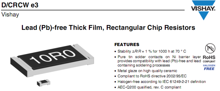
I chose to model a simple 0805 resistor. Begin by downloading the datasheet of the component. For reference, here is how the device looks in my Eagle library. If all goes well the 3D model will soon sit over the copper pads, within the silk outline.
From the datasheet It is important to get an idea of size and volume of the device. You usually find a photo on the front page.
More important are the exact dimensions of the device. I use a metric scale in my models, but feel free to use your favorite system.
Use and abuse of symmetry when possible. You can usually draw 1/4 of the device, and then by copying, mirroring and rotating get the full device.
I will show how I draw quickly a device. As you expect this is not the only way to model the resistor. Feel free to try and find your favorite method.
Since the device is very simple I will draw half of it. I start by the base. Remember that the origin of your 3D model corresponds to the origin of your Eagle part.
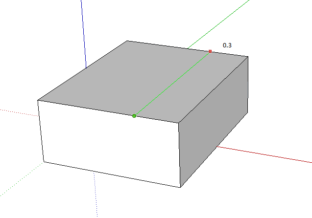
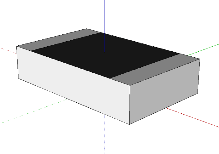
Then pull the surface up to give some volume. You get the shape of the resistor.
For aesthetic I add a line (cut the top face in two independent faces) to display the Nickel plating.
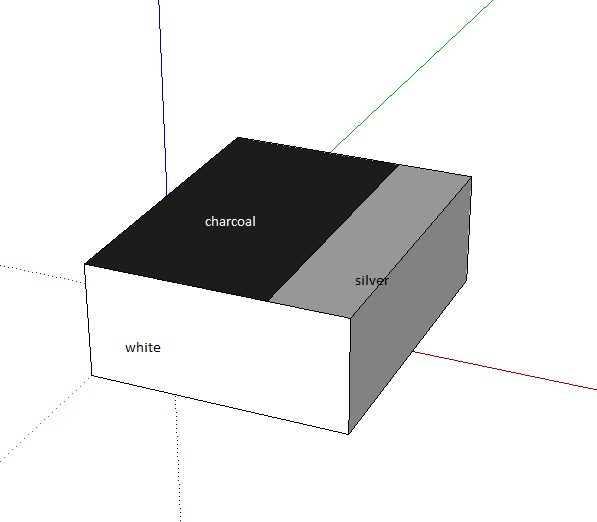
Then you can apply some colors on the model. I prefer the colors-named.
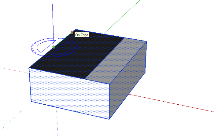
Finally I create the second half of the device by rotating+copy. There is no real mirror function in SketchUp, you need to copy the object, apply a -1 scale then move to contact. Rotating the object is easier. Press control key to copy the object (other wise you just rotate your object). Choose the center of the rotation carefully. It should be the origin here.
Then you can clean the model, remove unused lines created by the symmetry, remove the guides..
That was simple ! For reference I summarize the dimensions :
 Remember that all my models are scaled 1000:1 All the dimensions in m are in real mm.
Improved resistor model
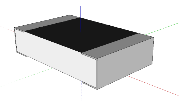
The first model was simple and quick, but not very realistic. If you have the device in your hand you know that it does not look like this, the contacts are made with a piece of metal, not some painting ! If your objective is to get a realistic picture out of eagleUp, here is how to improve the model.
For this example I take another approach and draw a section of the resistor. I chose 20µm for the metal thickness (it was not indicated in the datasheet so I picked a value).
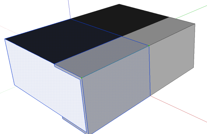
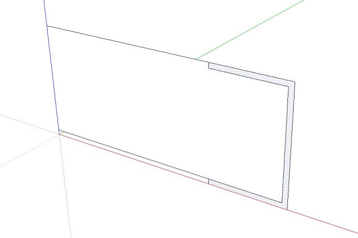 Then I pull the two faces, inside and contact.
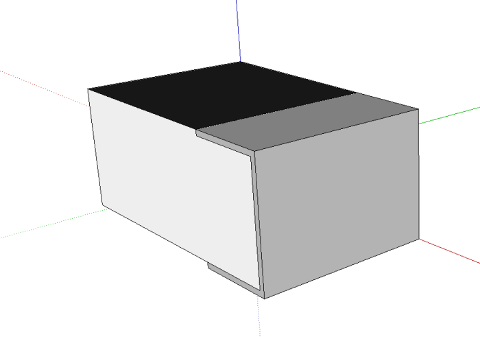 Select all, and control+move (copy) the design until you get the symmetry (use the corner endpoint for precise placement)
And finally a rotation gives you the complete device.
After a bit of cleaning you get a more realistic resistor. Feel free to add a value or any other detail in your model.
Orientation and axis
The orientation of your Eagle footprint and of the SketchUp model should be identical (or you will quickly notice it on your assembled model).
Modeling an IC
After this simple resistor model, let’s try to model an Integrated Circuit. I chose a classic dual operational amplifier in 8 pins SOIC package. You can find the datasheet here. In the last pages you can find the package mechanical description.
Before running into the sketch, you should decide how you will model your device. Here with this simple package I will model one half (the side with pins 1, 2, 3 and 4) and then mirror it to get the second half. Note: the extra bevel on the first half will be ignored as this edge is quite complex to draw in SketchUp and barely visible.
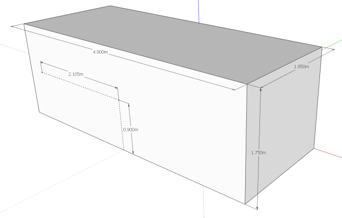
We begin by creating the plastic body of the device. Dimensions are 1,95 x 4,9 x 1,75 mm / meters. Place a guide on the location of the future pin 1 (shown by the red dot on the above picture)
Then we draw the pin somewhere else in the model (avoid drawing it too close from the body). The finished pin will be attached later to the body.
The gray face represents the pin section. The other lines indicate where the pin should end.
There is not much information in datasheets about the shape of the pins. Try to make it look like a real one. I indicate the dimensions I picked.
Then we build the pin with the Follow Me tool. You can find more indications on how to use this tool in this tutorial.
Real pins are curved, not angled ! Before using the Follow Me tool, you can add some tangent curves to your trajectory. Use large radius curves to get a proper bending of the pin. It is a good idea to delete unused lines close to your curves before using the Follow Me tool, so that the path selection is easier.
Here is how the final pin looks like.
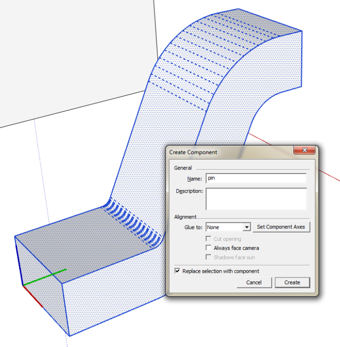
We make a component of the pin. This guarantees that all the pins of the model will look identical, and helps with the select and move commands. The pin will not merge with the body geometry. Select all the pin by triple clicking on a face. Then you find the create component command in the contextual menu.
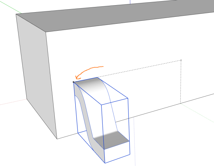
Time to assemble body and pins. Select your pin model (now appear in a large blue cube), select the move command and choose the top left corner of the pin and drag it to the guide you placed earlier on the body. It is easier to make a stop on a corner of the body and then to drag to the guide point.
You can now delete the guides (click on the dashed lines to select them).
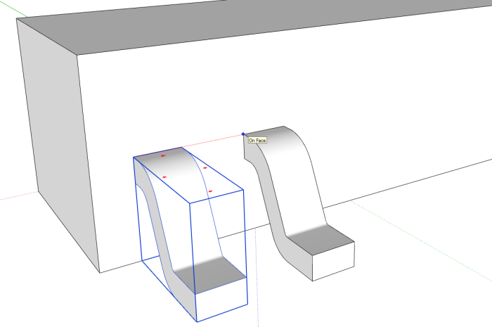
The advantage of having the pin as a component, is that we can copy paste it as much as we want and still be able to edit them all at once. Next we will duplicate so we get all 4. Select the pin and the move tool, maintain the Ctrl key pressed (copy instead of move), and drag on the red axis. Type 1.27 (the pitch of SOIC devices) and then 3x so that you get 3 copies regularly spaced.
We will now mirror the model to get the full model. Since the device is symmetrical, I use the rotation tool which is quicker than copy+symmetry. Remember to select all the model (Ctrl-A). The center of the rotation has to be over the origin.
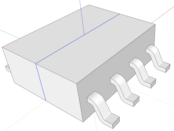
Press the Ctlr key to duplicate and rotate 180 degrees. For cosmethic reasons I delete the unnecessarily lines at the joint between the two halves.
Time to polish the model. The SOIC package is not so squared. If you want a realistic and nice looking device you can add the top and bottom bevels. I think it is easier to add these details at this step than on the half- or quarter- device.
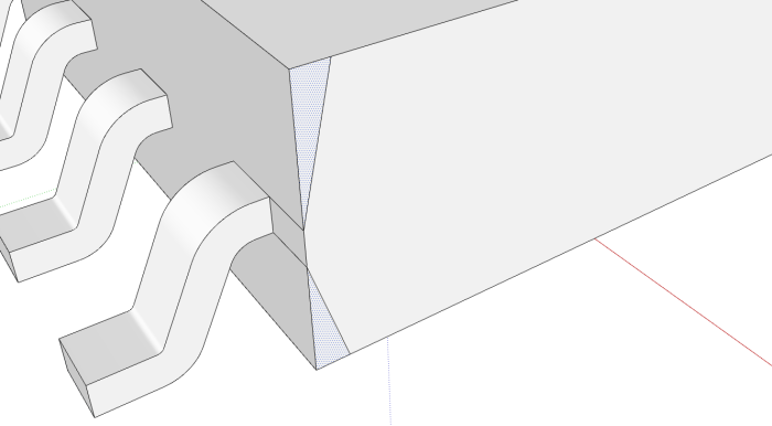 Use the Follow Me tool to cut the bevels. Begin by the top face and guide it all around the top face edges back to the starting point. You have to proceed in one step only.
Repeat for the bottom bevel. It is important to orientate properly the view before starting the Follow Me operation. This step is quite tricky and you may need several trials to get it good. Practice makes better.
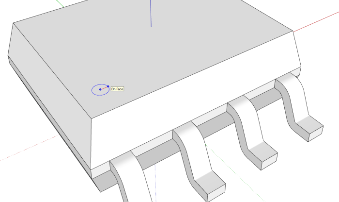
You can add the pin one mark. Draw a circle on the top face. Then push it down 0.05 mm.
The last step is to add a bit of color to the model. I use silver for the pins and charcoal for the plastic body.
Select the whole body by triple clicking on a face. Choose the paint bucket tool. Charcoal is under color-named. Then select a pin and double click on a face to edit the model. Select all and apply silver.
 How does it look ? Remember to save it in your /Eagle/model folder with the exact name of the Eagle package.
The first modeling of a package is difficult and slow. I hope this step by step tutorial helps you by showing in which order to proceed, and a few tricks. With a bit of practice you can get a precise and realistic model in 2 minutes. It’s worth it.
—–
I leave the comments open on this page so you can comment and ask directly here











I think it would be better if everybody draws all models in “real” size. Scale 1000:1 is not so good because then the shown dimension is wrong.
Hello Erich,
I can understand that changing the scale is not the most intuitive idea. But it has a huge advantage : you can draw small details otherwise impossible (try to draw the sub-mm curve of the pins with a mm scale ….). Sketchup is designed for architecture so it does no handle small dimensions as well as other CAD tools. When you set your template in meters, you enter the values with the keyboard as if they were mm. You don’t need to type the unit, just type the values.
Jerome
Ok I see! But if you import some CAD data then the dimensions have to be correct. But you can scale down the whole PCB by 1000 and then both should be of the same size.
Thanks for your work! It’s great! I will use it for my next projects and maybe I have some time (or I need some special models) to draw some devices and send you by mail!
It would also be neat to go the other way, from Sketchup to Eagle. Are you aware of any tools to do that? I find creating the land pattern for anything other than simple parts a real pain in eagle. In sketchup, it would be easy. If I could create it in Sketcup (just the pads first) and import it into Eagle as a starting point for the pads, that would be great! I could then continue to enhance the model in Sketchup to finish it up for eagleup afterwords.
Hello Mike,
I recommend you spend a bit of time practicing library creation in Eagle. Sketchup might give us a nice preview of the future integration of your project, but the most important is that it works ! And for that you need a proper package. Drawing one package should not take longer than 5 minutes with good habits.
You can follow the tutorial of Eagle, or some of the web like :
http://www.sparkfun.com/tutorials/110
Then when you draw a package there are some simple tricks to save time :
– use a proper grid, or enter the coordinate directly (use excel to calculate the list of coordinates)
– use and abuse of copy-paste
– for the outline, draw a rectangle, then edit the coordinates
– there are plenty of libraries available on the web (check cadsoft website) with common and uncommon parts
– there are also a few ULPs that automate the process
Jerome
Regarding the step or iges import. I found that sometimes freecad freezes when creating mesh from shape (maybe too complex model) and that “create mesh from geometry” works. I don’t know what’s the difference but the resulting model seems fine.
I’m using Eagle 5.11 and eagleUp 4.3. After running the ULP and then importing the .eup file into Sketchup the board is created correctly and the components are imported and scaled correctly but the components are not in the right place. Is there something that needs to happen in the component modeling process to ensure that the pins of the component align with the schematic in the 3d model. I did not use the “mirroring” technique described in the tutorial. I realize this is isn’t magic, but it might be helpful to understand in a bit more detail how to get this to work properly. I tried to google this before asking. Thanks!
Hello,

Check this image:
The resistor is represented horizontal in eagle (ie, pads on left and right sides).
Your model needs to match your package. If the model is not correct you can rotate it around te origin (select all, then rotate). It’s usually easier to access the origin by below.
Jerome
I like to use Camera >> Standard Views >> Top (or equivalent keyboard shortcut) and make sure it matches my Eagle library layout, which is always a top view. Then you just have to get the Z offset correct.
Thanks for the responses. So I guess the simple answer for ensuring the package gets placed correctly is this: ensure the origin placement in the EagleCad package matches the origin placement in the Sketchup model. Also, with respect to the top view in the manuf. mechanical drawing, in Skechup the positive blue axis represents out of the page, the red positive axis represents the right side of the package; and the positive green axis represents the top side of the package. Sorry if this was simple for most, but it wasn’t as obvious for me. Hope this helps others.
Resistors and Compinents are not showing please reply
Please detail your problem. Do you see the tracks and vias ?
Started putting my components in my GitHub:
https://github.com/NetForces/Hardware/tree/master/component_library
Available to anyone who wants them.
Very helpful for importing an iges into sketchup. You saved me a lot of hassle. Thanks for the excellent video