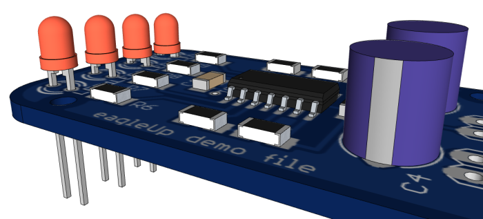
Recently, many users have reported issues with the model lacking the tracks and silk images. The issue was caused by a change in the recent versions of ImageMagick. We have now fixed this issue thanks to Edwin, and took this opportunity to improve even more eagleUp.

eagleUp 4.4 brings compatibility with ImageMagick 6.7.7 and Eagle 6.x. as well as with the previous versions.
Top and bottom textures are generated faster and will look better near holes.
Parts placement is more precise, with um resolution.
The EAGLEUP attribute gets a third parameter to modify Z-axis offset without modifying the 3D model. On the image above the Led have 0.5mm offsets. Syntax can include {part_name} {;{M}{Rxxx}} {;yyy.yy u}, where yyy.yy is the vertical offset (positive or negative float value) and u the unit. Unit can be mm, mil, mils, or inch. To move the part upward by 0.5 mm, add the attribute EAGLEUP with value ; ; 0.5 mm
The files are now handled with relative paths, so the eagleUp export folder can be moved around. This also helps with non-english characters, such as ö, ü, in the path (simply avoid them in the name of the export folder).
Two new options for the silk layers : none, and custom. In custom you can define your own mix of layers used for the silk. Type the layers separated with a space, for ex 21 25 51.
The new version of eagleUp can be downloaded here. Replace both the old ULP and RB files with the new ones.
First of all thank you a ton Jerome for designing this fantastic piece of software which allows us to harness the power of 3d.
My name is Dipayan Pal and I am an electronics system design engineer from India. Although I have access to highly priced ECAD softwares like ALTIUM (due to my job) but I use EAGLE personally for my own projects which I share with the open source hardware community. A few weeks back I designed a board which uses PIC microcontroller to log resistance data and transmit it via RS232 to the computer. For the case I used a generic housing one of our local suppliers provided. So I designed the PCB in EAGLE and then thought of using your software to generate the 3d board. Once I exported the file in sketch up I added few components which I was supposed to use. I used the dimensions provided by the housing manufacturer to create the boundaries of the 3d case. Everything fitted perfectly the lcd popped out exactly where it is supposed to everything was looking great until I discovered that the dc connector jack was colliding considerably with the housing. So I went back to the PCB files and fixed it. Now had it not been of your software I would have manufactured the same board which would have never fitted in my housing unless I manually extended the hole which would make the product look doggy and unprofessional. Since then I use EAGLE 3d for all my design I also use hdri rendering to generated photo realistic boards.
Currently I am working on my blog once it is done I will post you the link so you can check some of my 3d boards done by using your software.
Again thank you very much.
Hello
The eagleUp is working perfectly, but there is the problem of missing models from Sketchup. I made a simple PCB that contains a TQFP and pin headers, they are missing from sketchup when importing.
1- do you have the appropriate models in your model folder ?
2- is the name of the skp file matching the library footprint name ?
eagleUp works with your own list of models. You can find some ready made (for ex in the warehouse) but it is easier and faster to make them yourself. TQFP exist in multiple pitch and width.